
For many years at this QTH I have tried different wire antennas. Not being interested in rotary beams of the usual type, I have always use fixed wire antennas.
Over the years I came to the conclusion that for my particular purposes I needed something with gain that would work in more than one direction.
Having tried vertical beams and phased verticals all hanging from a nylon line, I decided to use the same nylon line to hold up a Lazy H antenna.
The Lazy H works very well of course, Bi-directional, low angle and gain, BUT its a bit too big to rotate to fill in the directions 90° from its broadside line of fire and I don't have the room to put up a second Lazy H.
It was while playing around with this antenna using the MMANA-GAL modeling program that I tried bending the ends of the top dipole down and the ends of the bottom dipole up, still keeping the open wire phasing line between the two dipoles and fed in the center. I eventually ended up with the ends of the dipoles joined together and the horizontal top and bottom parts of the dipoles very much shortened and tried feeding at the junction of the dipole ends, getting rid of the phasing line between the two dipoles.
This arrangement now reminded me of the VHF skeleton slot antenna that I had seen in an old RSGB handbook, but a search on the Internet turned up nothing for an HF version.
More adjustments in the MMANA-GAL program showed that the antenna should perform well on all bands from 30 meters to 10 meters.
To get the low angle take off, the bottom of the antenna needs to be about 15 feet (4.5M) off the ground. It will still work if the bottom is lower but with a higher angle of take off.
I purchased a Pump up mast 50 feet (15m) and a small cord operated rotator. The top horizontal spreader is fixed to this rotator and the whole antenna hangs down from there.
The MMANA-GAL program can be found here.
Below are the dimensions I used for the Lazy-H antenna.
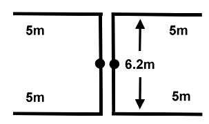
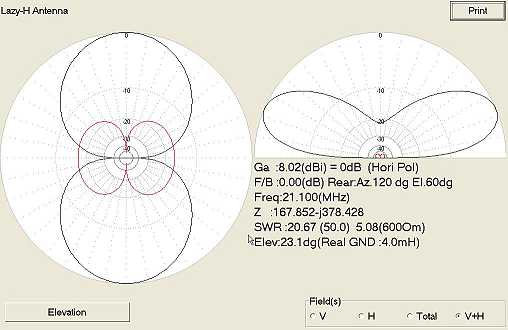
The plot below shows the gain and angle of elevation of the Lazy-H, as computed with MMANA-GAL. The antenna works well but is difficult to rotate.
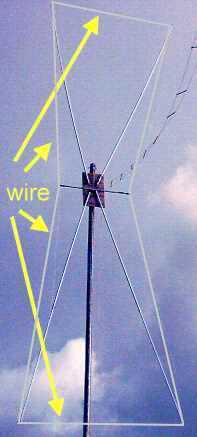
The photograph below shows the antenna installed at my QTH.
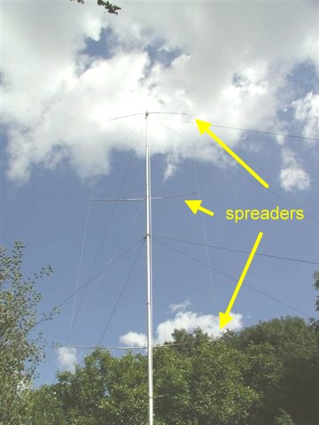
The top spreader is 50 feet above ground. The bottom about 20 feet above ground level.
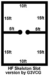
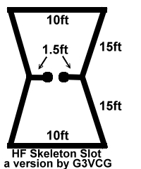
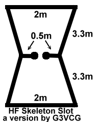
The drawing above shows the dimensions of my Skeleton Slot.
It can be easily rotated. It is bi-directional. It has high gain, low angle of elevation, and can work on all bands from 10 to 30 MHz.
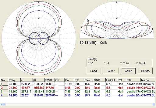
Below are the plots of the Slot for the bands 20m, 17m, 15m and 10m.
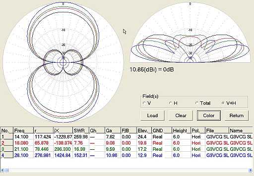
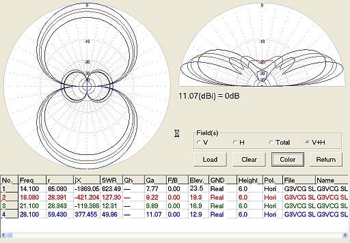
Below is shown a "BowTie" version.
It has slightly higher gain and lower angle of elevation.
The corresponding plots are shown below.
This picture shows the bowtie version at GW3RQT(SK)'s
The small marine ply support for the spreaders can be seen in the center.
The short horizontal bamboo in the center is to support the dog bone insulator and the open line feeder together with the vertical wires coming from the four corners.
Alan GW3RQT(SK) uses the same antenna but with smaller dimensions as his mast is only 30 feet high.
It is designed for 15m but works well on all bands from 10 to 20m.The plots are shown below.
He uses spreaders for the diagonals mounted on a rectangular piece of marine ply with U bolts.
The center is then raised to the top of the mast which gives a height of 15 feet from the bottom of the antenna above ground.
The antenna is very easy and inexpensive to make. For the sake of clarity, the constructional details are on another page.
The skeleton slot antenna is very cheap and simple to make - mine consists of three bamboo spreaders and copper wire!! It is fed in the middle of the center wire with open wire line which is taken to an antenna tuning unit in the shack.
Results have been excellent and quite a lot of DX has been worked on digital modes using 50 watts even through the odd pile up .. With such a broad horizontal pattern I only need to turn the antenna 90° to get pretty well full coverage of the world . For example with the antenna in a NE/SW direction, stations from K4 down to LU and JA down to VK6.
Have fun 73 Don G3VCG
My e-mail address is here